Introduction
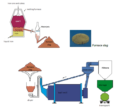
Orcem in the Netherlands manufactures a special concrete called ECO2cem. One of the advantages of ECO2cem is that during the production process less CO2 is produced, making ECO2cem a very environment-friendly product. Orcem has two production plants, one in the Netherlands and one in Ireland (Ecocem). Both plants have used the VCM system from SPM Instrument for years with the LR/HR and dBm/dBc techniques; however, Orcem and Ecocem were both very interested in the new SPM HD technology. After long discussions, both plants decided to switch from the VCM system to the newer Intellinova system – and with fabulous results, which are highlighted in chapter 2. To produce ECO2cem, Orcem uses furnace slag. This slag is a waste product of a steel mill. Iron ore, calcium, and cokes are melted in a blast furnace at 1500°C, producing a liquid cast iron. Due to the low density of the non-iron parts, called furnace slag, the slag floats to the surface and is used for the production of the ECO2cem consisting of mainly calcium, aluminum and silicon.
Figure 1. Overview of the production process.
2 Conclusion and summary
During the period from May 2014 until September 2014, a serious problem was detected well before any serious consequences occurred. Readings from the input shaft of the gearbox showed a clear bearing damage. Approximately three months before the alarm, SPM HD measurements indicated this bearing failure. After this initial bearing problem, another problem evolved on the output shaft and the decision was made to replace the complete gearbox with a renovated one. The gearbox was replaced on the 5th of June, resulting in green condition evaluation for all measuring points again. Yet another problem caught was a fan bearing that needed to be replaced because it had been damaged during installation. Since the previous online system (VCM) was replaced with the Intellinova series of online systems, the SPM HD measuring technique has proven able to measure bearing damages with exceptional prewarning times, giving the customer the opportunity to plan for repair/exchange of the defective machinery and the ability to check the quality of maintenance work done by contractors. For more information about the different cases, please refer to chapter 5.
3 Application description
There are many different types of mills; ball mills, rod mills, SAG (Semi-Autogenous Grinding) and autogenous mills. In a ball mill, steel or stone balls are mixed with the ore and during rotation of the drum the ore is ground, by friction and compression, into a suitable fineness for the next step in the process. The main component of all mills is a rotating drum, turning with a suitable speed, gearbox, and motor. The mill is a very important part of the milling process in the cement industry. In many cases, the entire process can be severely limited or completely stopped if the mill ceases to operate and close observation of mill equipment condition is therefore essential. An unplanned stop must be avoided at almost any cost. Many years ago, SPM Instrument installed a VCM system on the mill gearbox and motor.
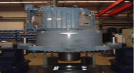
Image 1. The ball mill at Orcem Netherlands.
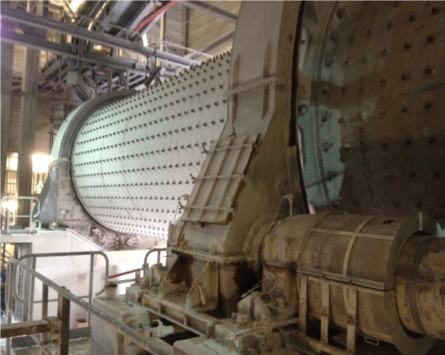
Image 2. The gearbox, just renovated, with the shock pulse and vibration sensors.
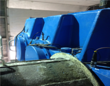
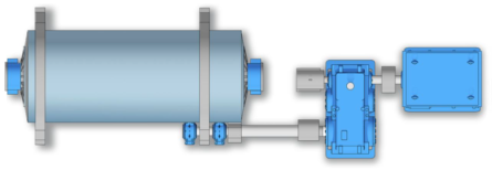
Image 3. A principal overview of the ball mill.
4 System setup
4.1 Measuring equipment
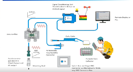
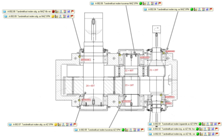
Besides the gearbox, the electric motor and the support bearings of the girth wheel are equipped with shock pulse and vibration transducers. Other applications monitored are a fan and a wind sifter. In total, sixteen shock pulse transducers and eight vibration transducers are connected to an Intellinova standard system. Shock pulse transducers are installed on all bearing positions. Vibration transducers are installed on the input shaft DE (V) and output shaft NDE (H/A). RPM is measured using a proximity switch facing the motor shaft.
Figure 2. Location of shock pulse and vibration measurements at critical points.
4.2 Condmaster setup
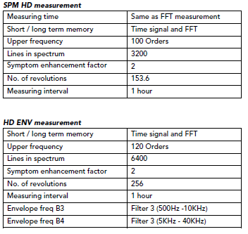
Settings used in Condmaster Ruby 2014.004:
5 Case descriptions
5.1 Case #1 – Gearbox input shaft, NDE
The first signs of bearing damage were visible around May 5th, 2014, using only the SPM HD measuring technique. The SPM HDm value was fluctuating, and when looking at the spectra, the first signs of BPFO harmonics could be seen. Later the HDm and HDc values were both increasing and a significant increase was seen from the 29th of July. The decision was made to plan for a replacement. Around September 2014, the spectrum was full of BPFO harmonics.
Figure 3. SPM HD trend graph gearbox from March 2014 till October 2014.
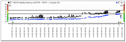
Figure 4. SPM HD trend graph from September 2014 (zoomed in).

Figure 5. The SPM HD spectrum showing a clear BPFO with harmonics.
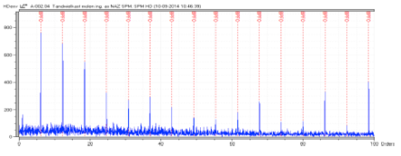
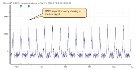
Figure 6. Time signal showing BPFO impacting.
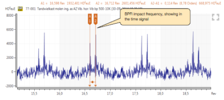
The decision was made to implement the newly introduced HD ENV technique. Because there was no vibration transducer on the input shaft NDE, the decision was made to install a transducer with a magnet base at that point in order to acquire extra data on the developing bearing damage. Two bands were used; Filter 3 (500Hz -10KHz) and Filter 4 (5KHz – 40KHz). The transducer was installed on the 25th of September. When analyzing the spectra and time signal, there were clear signs of an inner race damage. The time signal showed a clear BPFIM signal. Below is the trend graph from the same measuring point, using the HD ENV technology.
Figure 7. Trend graph of the HD ENV B3 measurements on the gearbox from September to December.
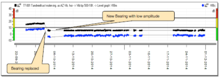
Figure 8. HD ENV B3 spectrum showing BPFI with sidebands.
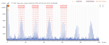
Figure 9. HD ENV B3 Time signal showing BPFI and modulation.
The pictures show damage on the inner and outer raceway; however, the inner raceway is the most damaged. The outer race was not visible in the HD ENV measurements. On the other hand, the inner race damage was not visible on the SPM HD measurements. This demonstrates the added value of using complementary measuring technologies like SPM HD and HD ENV.
Image 3. Outer raceway.
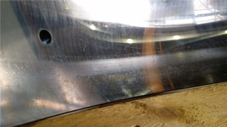
Image 4. Inner raceway with extensive damage.
5.2 Case #2 – Gearbox output shaft DE
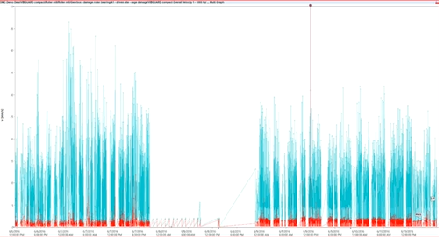
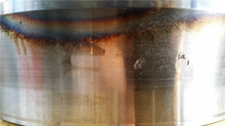
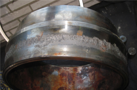
The first signs of bearing damage were visible around the end of June 2014, using the SPM HD measuring technique. From that date on, the BPFI trend was increasing and fluctuating. From the end of March 2015, the values elevated even further. The gearbox was replaced on June 5th and this resulted in a green evaluation for all measuring points again. The bearing was examined and the inner race damage was confirmed by the gearbox supplier.
Figure 10. SPM HD trend graph.
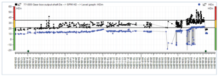
Figure 11. SPM HD spectrum with BPFIM markers (25-4-2015).

Figure 12. SPM HD Time signal showing BPFI and modulation.
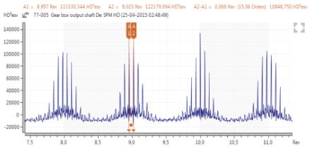
Image 5. Inner raceway with extensive damage.
5.3 Case #3 – Exhaust fan DE
The drive end shock pulse measuring point has been elevated since measurement started; the alarm and alert levels were already adjusted in the past. The bearings for the exhaust fan were replaced because the shock pulse spectra started showing the BS and BSFM defect frequencies from the 2nd half of 2014.
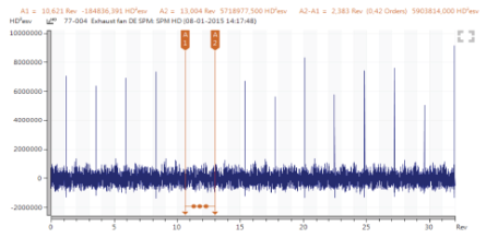
When the new bearing was installed, the HDc readings increased further, meaning lack of lubrication and therefore high load on the bearing. This normally indicates the bearing mounted incorrectly. When the spectrum was investigated, the FTF and BS frequencies were visible. The service provider who replaced the bearing was called and the decision was made to change the bearing once more. After this 2nd exchange, the overall value and the cage rate (FTF) evaluation dropped to normal values again.
Figure 13. SPM HD trend graph; in the red rectangle are the measurements after the 2nd replacement.
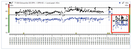
Figure 14. SPM HD FTF trend graph.
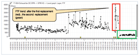
Figure 15. SPM HD zoomed spectrum with FTF markers, 1st new bearing.
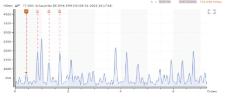
Figure 16. SPM HD Time signal showing FTF peaks, 1st new bearing.
6 Economic justification
The combination of vibration and SPM HD shock pulse measurement is ideal for this type of application. The shock pulse technology is very suitable for the detection of bearing damages in “noisy” environments like the gearbox in this case study. Vibration technology is optimal for low frequency related fault conditions like unbalance, loose gears and misalignment. Thanks to the sensitivity of the SPM system and the long pre-warning times, maintenance actions could be planned well in advance. The contribution of the condition monitoring system is evident as it was able to detect two bearing damages during the warranty period. As a result of this, the gearbox was replaced without any cost for Orcem.


