Five Minute Facts
Condition Monitoring Technologies – Pros and Cons of the Top Five
Overview
There are several different technologies that can be used, alone or in combination, to monitor the condition of your machinery from a predictive maintenance (PdM) perspective. The criticality of the machine affects the number of such inspection-type technologies that are applied to a given failure mode. The more critical the machine and the more critical the failure mode, the more redundancy you will want in the inspections. For the top 20% of the machines on your criticality list, there may be four or five different PdM technologies covering the machine. For the next 30%, you may have the two best technologies for each failure mode. And for the balance of the list, you may only have one such technology for each failure mode. In this blog article, we will focus on five main options: 1) infrared thermography, 2) ultrasound, 3) oil analysis, 4) vibration analysis, and 5) motor circuit analysis.
Infrared Thermography

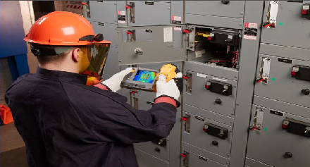
Manufacturers of infrared cameras are now making low-cost solutions of adequate image quality that work great for infrared programs just getting started. This technology is capable of finding both electrical and mechanical defects, and it is very easy to understand and accept.
- Electrical defects – Most defects in electrical apparatus create localized heating, which is easily detected with an infrared camera. Problems with electrical apparatus are almost always due to loose and/or dirty connections.
- Mechanical defects – Defects like misalignment, v-belt and sheave problems, bearing defects, and lubrication problems all produce heat within the components. This heat is easily detected by the infrared camera.Note: Infrared thermography is not the most preferred method for detecting mechanical defects, as the defect is already significantly down the defect progression path before the localized heating begins to occur.
Ultrasound

This inspection method is both powerful and inexpensive; however, as mechanical inspection technologies go, it is the biggest bang for the smallest buck. It is also a good choice if you want to have operators, mechanics, and electricians participate in the PdM program. Ultrasonic devices are used to listen to:
- Rotating machinery – to detect bearing faults, gear problems, electrical problems in motors, lubrication issues, and cavitation in pumps.
- Electrical apparatus – to detect the presence of arcing, tracking, and corona. Arcing and tracking are both damaging to the electrical equipment and increase the potential for arc-flash
- Stationary equipment – to find defects in valves and steam traps
Ultrasound also adds value to your lubrication program, by eliminating the common problem of over/under lubricating bearings. The ultrasonic energy coming from a bearing can help determine whether the right amount of grease has been added to the bearing.
Challenges
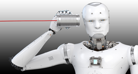
The ultrasonic device takes sounds that are above the range of human hearing and transforms them into something we can hear. The main challenge is that the analysis is qualitative and is based on the trained ear of someone familiar with the ultrasonic signatures of healthy and unhealthy equipment. Another challenge is that while it is powerful in finding high frequency problems, it is powerless against low frequency problems like imbalance, misalignment, and looseness. So, ultrasound is not a like-for-like replacement for vibration analysis (discussed below).
Oil Analysis
Oil analysis is one of the most commonly used PdM technologies. Its original application in the manufacturing world was to detect water and the depletion rate of additive packages in the lubricant. This technique has since been expanded to include the detection of changes in:
- The lubricant chemistry, itself
- Wear particles (indicating defects in the components)
- Contaminants from outside of the lubrication system (indicating a sealing problem or poor storage and handling practices)
There are several tests for each of the aspects. The best oil analysis program identifies the reasonable and likely failure modes for each of the machines that qualify for the oil analysis program, and then specifies to the oil lab which tests are to be run for which samples. This declaration of tests for a given sample is called a “test slate.”
Vibration Analysis

By far, the most powerful and comprehensive PdM technology for detecting defects in rotating equipment is vibration analysis. The vibration signature is collected from a rotating machine and then analyzed by a person. The signature is a collection of spikes called “peaks.” These peaks represent different forces at play on the rotating drive train.
The analysis of the peaks is the linking of their frequency to the known frequency of rotating drive train defects. For example, shaft misalignment happens at a different frequency than gear problems do, or bearing faults, or even electrical problems in motors. Each of these has their frequencies, and each has their own patterns in the vibration signature. Therefore, the test slates are not the same for all pumps, as they operate in different environments and under different running conditions.
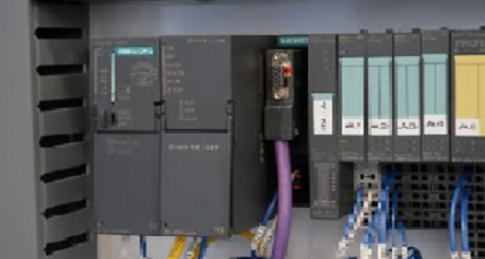
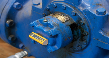
The data can be collected via different devices. Some are hand-held and can be carried from machine to machine during data collection, while others are permanently installed devices that connect to the PLC network in your plant and provide continuous monitoring.

Motor Circuit Analysis
Last, but not least, this specialized PdM technology focuses on motor circuitry. The motor circuit includes the motor windings and the wires that connect the motor to the starter. The entire circuit needs to be tested to detect the presence of insulation problems, contamination problems, and other mechanical issues with the motor.
- Offline MCA – This is performed when the motor is off, and the rotor is secured in place. These offline tests help the analysts detect any insulation issues between the three phases of the motor, as well as any issues between the phases and the electrical ground of the motor.
- Online MCA – This method tests for the presence on any torsional loading on the motor. Most torsional loading comes from inside the motor due to loose or broken rotor bars, or broken welds on the end ring of the rotor. However, some torsional loading can come from outside the motor, such as misalignment, coupling problems, or in extreme cases, even bearing faults.


