How We Diagnosed Our Cooling Water Pump Gearbox
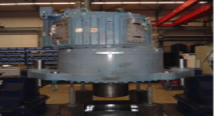
This case study comes from a custom-made, four-story-high pump at Engro Fertilizers.
There is a bevel gearbox driven by a steam turbine, and then the main pump. The input speed is 5,143 RPM, and the gear ratio is 8.64. The pump steps down to 595 RPM. The main shafts are supported by sleeve bearings whereas the vertical shaft is supported by roller bearings, and this is a strange combination.
The input shaft has sleeve bearings on both sides. It drives the next gear, which has sleeve bearings and one roller bearing that acts as a thrust bearing. The bevel gear has roller bearings on both ends. There are not many points where we can take vibration readings. Many of the points where we’d like to take vibration are inside the gearbox, making this a bad design.
Unless I invest in an online monitoring system (prohibitively expensive for this unit), I cannot access the inboard bearing. There are so many gear mesh frequencies that it’s impossible to tell what’s happening with a particular bearing. We also have a bearing with a backstop, which is essentially a sort of bearing which has grooves on it. If it starts rubbing, which often happens, it’s impossible to differentiate whether it’s the bearing, the backstop, or the gear mesh frequencies. So this is a difficult pump to diagnose.
Series of Events
There is a lot of literature available on straight gearboxes, but not much on bevel-type gearboxes. You have to rely on your own research and experience. Machinery is 80% common sense, which you use to apply the 20% knowledge.
The pump was commissioned and installed in 2010. It was in continuous operation from October 2012. In January 2014, we started noticing abnormal noise and vibration from the gearbox. But we couldn’t see anything apart from an increased gear mesh frequency, meaning the gears were meshing at an abnormal rate, or possibly more load on the gearbox.
We tried changing the RPM, checking the flow, and checking the process parameters, but we couldn’t find any abnormality. The bearing temperatures were fine, and the roller bearings were fine.
We shut down the machine, opened the hatch, and checked the backlash, which had increased. That shouldn’t happen in a new gearbox, not until there is abnormal wear. But we didn’t see any wear on the gears. They were as good as new. We thought maybe the bearing clearances had increased, but everything was fine. We decided to keep it in operation and continue to observe. After a week, the noise disappeared, and we eventually forgot about it.
In March of 2014, one of our main gas turbines tripped, actuating a tripping of this plant. When we started it up again the next day, we heard a loud cracking noise from the gearbox. This time, we decided to shut the machine down again and pull the whole unit apart.
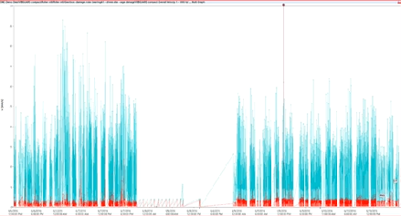
Before I get into what we found, have a look at this waveform (shown at 12:42). Seven years of experience has taught me to always look at a gearbox in its waveform. With gearboxes, spectra can only give a basic idea of what is happening. This is commissioning data, and everything looks fine.
This waveform (shown at 13:30) was taken in March of 2014, right before the shutdown. But note the mistake in the time between the waveforms. If you are using any kind of software or equipment, make sure you set it upright so you can get consistent data. Then, make sure your software does not override it (software often increases the resolution of the spectrum at the expense of the resolution of the waveform).
This is what it’s supposed to look like (shown at 16:48). What we’re seeing are load increases followed by load decreases.
During rotation, the gears are moving away from each other and then back toward each other. That’s the simplest explanation. What could cause this? The first thing that comes to mind is bent shaft. But we didn’t see a bent shaft during our earlier inspections.
What we found was that the gear was loose on the shaft. Because there are no points on the gear to apply a dial indicator, we hadn’t known it was loose. Our focus had been on the shaft itself.
So what happened? After we started it up after the tripping, the gear chipped. An entire part of a tooth chipped off.
Observations
We were still trying to understand what happened to the gear.
When inspecting, we used a crowbar to move the gear while holding the shaft still. We noticed that the gear moved away and back. That’s when we realized the gear itself was loose. This explained the amplitude modulation.
But this is not a periodic modulation. Sometimes the gear would get stuck and show a periodic modulation, and sometimes it would just go loose, and there would be no modulation at all.
The key that was supposed to prevent the gear from rotating on the shaft had extruded on one end due to high torque and loose pinion.
It’s expensive to keep a spare of this gear, so no one keeps them. We simply filed the gear, making sure it was even enough because there was still 60% of the gear length left. We put it back in the machine, and it worked well for six months until the new gear arrived.
Let’s take a look at why the gear broke. It doesn’t make sense for this gear to break because the tooth was 12 inches long. Why didn’t it break from the end? Why didn’t the whole gear chip off? It broke because of the way it moved on the shaft because there was an offset error and angular misalignment. When this happens, the entire load can shift to one corner.
We have four of these pumps at our plant; two are driven by motors and two by steam turbines. At any given time, three pumps are in operation. The steam turbines produce a lot of steam. When one unit trips, another starts up. But there is an oligodynamic valve which takes about 40 seconds to close, during which there is a backflow. We have a backstop, but it decelerates the pump. A pump that would normally stop in a minute and a half stops in less than 10 seconds when this happens. When that happens, the entire load shifts from a normal position to one end of the gear. That’s when it chipped off. That’s one thing we fixed after this problem. We made sure we had a faster-responding unit that could close the valve as soon as possible.
One thing we can learn from this is the importance of factory acceptance testing. Once the vendor has told us a part is API compliant or EGMA compliant, we don’t usually go in and probe how compliant they are. The 50-page document they give you says that they have exceptions to EGMA, but no one asks for details. That’s sometimes the difference between a good machine and a bad machine. Ask for a list of the exceptions and perform factory testing.


hello Alli, thanks for sharing us your important experience with this problem. could you please give help to resolve my problem it seems like the same problem you had. there was a high vibration readings on lube oil pump connected to Gear box for gas turbine generator for four years ago since the installation of the new pump supported by two sleeve bearings and operating at 900RPM, before 40 days ago the teeth and the bearing NDE side pump was damaged after pre oil filter was clogged with metallic debris. after that new pump was installed but the vibration get… Read more »