Incorrect settings in a Variable Frequency Drive (VFD) application have an impact on the windings of an electric motor. When a drive is not set correctly, or not tuned when not using straight volts/hertz settings, stresses occur between the turns in a winding. In some cases, this will appear as small Partial Discharges (PD), and in others it can be increased leakage between turns. When these conditions occur, they introduce small current discharges that effect the air gap magnetic field of the motor.
The study, which was published at the Institute of Electrical and Electronics Engineers’ Electrical Insulation Conference as the “Evaluation of Stator and Rotor Interturn Stress with Electrical Signature Analysis in Variable Frequency Drive and Wind Generator Applications,” [1] was pursued following a prior study on discharges in a vacuum.[2] Observations of discharges associated with windings being tested with an Electrom iTIGII PD surge tester (iTIGII) in a vacuum chamber, testing was performed on windings in application using both the iTIGII and an EMPATH Electrical Signature Analyzer (ESA). Where there were signs of PD in six of ten 0.5 MW flywheel storage devices at near-vacuum a specific signature associated with ‘winding shorts’ was observed. A review identified some issues with both the settings on the VFDs and the filters associated with the machines.
The videos associated with the discharge and testing can be found in the RELIABILITY CONNECT article: Flywheel Storage: Electrical Reliability
The discussion of the signatures associated with an inter-turn short and related research has been around for some time with the first identification of this type of short in an IEEE paper published by General Electric in 1997[3] which identified negative sequence currents as shorts developed in a motor on a VFD. The first publication of the associated formula for detection was by Joksimovic and Penman in October 2000, in an IEEE paper, “The Detection of Inter-Turn Short Circuits in the Stator Windings of Operating Motors,” [4] which introduced the spectral equation (eq. 1).

The work primarily was performed by university and corporate research in laboratory environments with induced faults, as it was determined that winding shorts would occur too rapidly for detection prior to failure. While a literature search turned up multiple such studies each year following 1997, none looked further than an actual arc-short between conductors. Following the observations on the flywheel study a review of historical data was performed by MotorDoc LLC related to machines that had experienced both bearing discharge failures (bearing fluting) and winding faults on VFD applications and a correlation was identified.
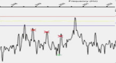
The next step was the identification of existing conditions which included three 600 horsepower, 460 Volt, 4-pole electric motors. Initial testing showed as Figure 1, which were also close to several bearing frequencies, and definite calculated winding stress peaks were found. It was determined that if we had not been looking for these frequencies, they might have been erroneously identified as being associated with the bearing peaks. The drives were then tuned, and findings were similar to those found in Figure 2.
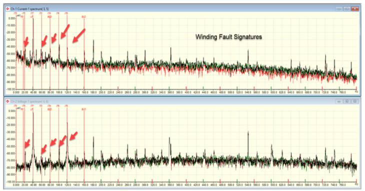
Figure 1: Winding Stress Peaks associated with drive set incorrectly (operating at 40 Hz).
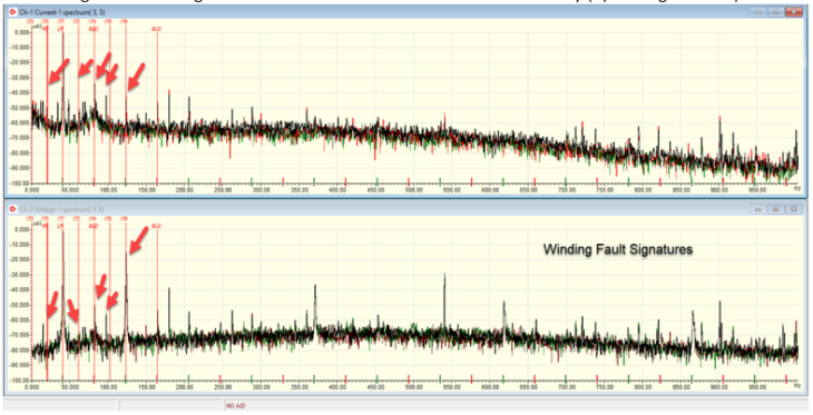
Figure 2: Winding Stress Peaks decreased significantly in same operating conditions after drive set correctly (40 Hz).
The study was then performed on a larger population of 67 motors ranging from 10 horsepower to 300 horsepower 19 motors were found to have the winding stress signature. All of them had incorrect drive settings while the remaining motors did not show significant issues and had correct drive settings. Changing the drive settings eliminated, or significantly reduced, the stress signatures. The 2020 IEEE paper is the first technical use of the term ‘winding stress’ to describe this class of early detection.
Conclusion:
The importance of distinguishing the previously described ‘winding short’ signature in ESA as ‘winding stress’ cannot be understated. When reviewing data related to the stator, a winding stress signature can identify the severity of a defect. For instance, slot sparking in high voltage motors will also show as a winding stress defect, which means a signature related to the stator winding and a winding stress signature would indicate stator coil movement with sparking.
In the upcoming article we will discuss the second part of the study which relates to the identification of loose and missing slot wedges in medium, high voltage, and other form-wound motors and generators.
[1] H. W. Penrose, “Evaluation of Stator and Rotor Interturn Stress with Electrical Signature Analysis in Variable Frequency Drive and Wind Generator Applications,” 2020 IEEE Electrical Insulation Conference (EIC), Knoxville, TN, USA, 2020, pp. 274-277, doi: 10.1109/EIC47619.2020.9158738.
[2] H. W. Penrose and M. B. Dreisilker, “Evaluation of Offline Partial Discharge in Vacuum Environments,” 2019 IEEE Electrical Insulation Conference (EIC), Calgary, AB, Canada, 2019, pp. 364-367, doi: 10.1109/EIC43217.2019.9046618.
[3] G. B. Kliman, W. J. Premerlani, B. Yazici, R. A. Koegl and J. Mazereeuw, “Sensorless, online motor diagnostics,” in IEEE Computer Applications in Power, vol. 10, no. 2, pp. 39-43, April 1997, doi: 10.1109/67.582451.
[4] G. M. Joksimovic and J. Penman, “The detection of inter-turn short circuits in the stator windings of operating motors,” in IEEE Transactions on Industrial Electronics, vol. 47, no. 5, pp. 1078-1084, Oct. 2000, doi: 10.1109/41.873216.


