Introduction
Pumps, fans, and compressors account for over 60% of loads in industrial and processing industries, while medium voltage motors over 200 horsepower account for 1% of the motor population and 45% of electric motor energy consumption. In the 1990s there was a significant focus on the application of Variable Frequency Drives (VFD) with motors under 600 Volts. It is estimated that less than 5% of the potential applications of medium voltage VFDs has been realized.
Since 2010 there have been significant improvements in medium voltage VFD technology with a focus on the impact to the electrical system. While smaller electric motors have limited impact on power quality, including harmonics, larger motors have a significant impact, depending on transformer capacity. However, power quality is not the only application challenge that must be reviewed before, during, and after an application has been realized.
Quality Assurance
VFDs rated over 600 volts tend to carry a significant initial investment in both purchasing and installation. The development of a specification and commissioning is vital to successful and reliable application. Many manufacturers provide ready-made specifications and commissioning documents that can be adopted and modified to suit. The quality assurance reviewer should be an employee or consultant who has knowledge of drives and the associated application and is not associated with the supplier or installer.
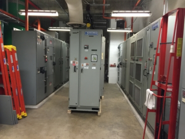
Items to be considered prior to ordering or selecting a drive include:
- Determine the associated controls and feedback to ensure there are proper communications, and that inputs and outputs are available.
- The existing cabling should be evaluated to ensure that shielded cables are installed and in good condition.
- The electric motor should be evaluated to ensure that it is in good condition. Determine if it needs to be replaced, reconditioned, or rewound to inverter application.
- The driven equipment and system should be evaluated in order to determine working condition and operating requirements, such as minimum and maximum speeds.
- Natural frequencies should be determined, if possible; otherwise this can be included as part of commissioning.
- A preliminary power and power quality study should be performed per IEEE Std. 519, “IEEE Recommended Practice and Requirements for Harmonic Control in Electric Power Systems.”
- Select line and load side filters as recommended by the application and/or manufacturer.
The drive can then be selected and any additional work performed based upon the preliminary review of the application and a checklist for the commissioning developed and agreed upon by both the owner and supplier. In some cases, it may be in the owner’s interest to perform a factory test on the drive to ensure that it properly operates during the burn-in tests.
During the installation, such items as the following need to be considered:
- Ensure proper labeling of all control wires and cabling.
- Ensure that the mounting strength meets the manufacturer’s requirements.
- Verify that the cabling and splices are in good condition by performing insulation resistance and power factor testing for long lead lengths.
Once the installation is complete the drive must be commissioned. This includes properly tuning the drive (for anything other than volts/hertz), both statically and dynamically, before coupling to the load. The direction of rotation should also be set. The load can then be coupled and the motor operated across the expected speed range, watching for resonance frequencies. These can be bypassed using the ‘jump frequencies’ in the drive that will cause it to stay away from the frequencies that can damage the associated equipment. If the motor speed bounces around the load point, the gain can be adjusted to reduce the chance of significant torque ripples that can damage the motor and load.
Medium voltage drives often have a large number of settings available for programming. Most of these will not be used and are available depending on the load and operating requirements. However, a few that should be considered are the ‘ride-through’ settings that will cause the drive to trip when the voltage drops below a threshold (usually +/- 10% of the drive voltage rating), especially when other loads are brought online that cause significant voltage drops during starting.
Once the system is set, a post power study and harmonics analysis should be performed while the system is operating, and these results should be compared to the initial study done in similar conditions. During the study, it may be found that the motor can be run at less than full speed to optimize the application, such as reducing turbulence by running with less air or water flow. The maximum and minimum operating speeds can then be locked in to both the drive and any associated controls.
A Few Reliability Considerations
When performing the harmonic study, it should be considered that while voltage harmonics are reviewed based upon THD (Total Harmonic Distortion), current limits are determined as TDD (Total Dynamic Distortion). The TDD is calculated based upon a percentage of the maximum kVA (kilo-Volt Amperes) of the circuit branch. The combined harmonics have an impact on the ‘true power factor,’ which will be less than the apparent power factor. The result will be an impact on transformer loading and voltage drop when other loads are brought online. Other parts of the system may be affected by power quality concerns, including other systems connected to ground.
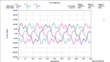
Drive systems require that a common ground exists between the motor and drive. This is accomplished by running a ground conductor back to the drive, while code also calls for a ground conductor from the motor to local ground. If unshielded cable is used, this can cause a ground loop and a resulting high common mode voltage and current on the motor and other metallic surfaces that can affect control and protective systems. This can be evaluated by measuring the current on the ground lead, which should be 1/1000 of the kVA of the maximum load seen by the motor. This condition becomes a safety concern if issues exist with the ground system.
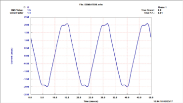
Any control cables should be located away from power cables and, if in cable trays, the power cables should be separate from each other to reduce the chance of induced voltages. When induced voltages and grounding issues become significant enough they can affect other machines and cause damage, such as bearing fluting and winding faults, similar to what would happen if the motors were operated on drives.
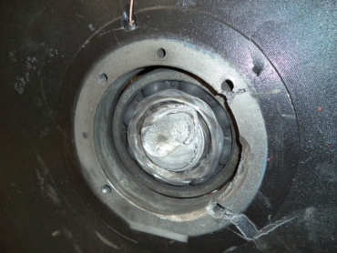
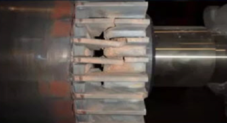
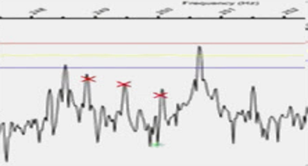
In the case of the motor and drive combination, especially high inertia loads such as large fans, improper drive tuning can cause torque ripple serious enough to break the motor or load shaft, gears, or couplings. This can be seen through technologies such as electrical signature analysis or vibration analysis.
Also, in high inertia loads the deceleration settings of the drive should be set correctly so that the load does not overdrive the motor, which can cause the drive to trip when stopping or changing speeds. This is due to the motor generating voltage back into the system.
Conclusion
Medium voltage drives can have a significant impact on energy consumption in fan, pump, and compressor applications. When developing the application, the owner should perform quality assurance and some analysis to ensure that the applications are reliable and safe. The commissioning of the medium voltage drive is an opportunity to prevent problems with the application, mechanical, and electrical systems.



Nice and clear article on application of large drives such as medium voltage drives. You might want to include the cooling method, circuit breaker and transfomer associated withe drive as well.