Before explaining the cross-coupled forces generated by the journal bearing, it is worth reviewing and understanding some key concepts on how the journal is located within the bearing and what forces are acting on the journal.
How the Journal is Located Inside the Bearing
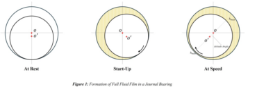
Figure 1 shows three different positions of the journal: At Rest, Start-Up, and At Speed. When the journal is At Rest, there is no oil separating it from the bearing, and the journal is resting on the surface of the bearing. When it begins to rotate (Start-Up), it first climbs the wall of the bearing in a direction opposite to the rotation due to the friction force between the journal and bearing metal surfaces. As soon as the friction force component in the direction of the load is overcome, the journal falls down the wall and crosses to the other side of the bearing. As speed increases, the journal draws more oil into the converging wedge until it is completely supported on a full film of oil with no metal-to-metal contact (At Speed).
Forces Acting on the Journal
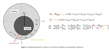
As the journal speed increases, it starts dragging more oil into the converging wedge, creating hydrodynamic pressure. Many factors affect the distribution of hydrodynamic pressure and its maximum value. However, let’s focus on the line of action of the pressure force. Referring to Figure 2, and ignoring all dynamic terms for a moment, we can examine the pressure force (P) and its line of action, which acts at an angle to the direction of the load (Pstat). It is not within the scope of this article to determine the angle between the pressure force and load. The main idea here is to show that the pressure force will have two components: one upward along the (-x) axis (Px), counteracting the load (Pstat), and the other component (Py) along the (+y) axis. This force tends to push the journal toward one side until the equilibrium position is reached.
Now, the reader may wonder what counteracts the pressure force component (Py) along the side until the equilibrium position is achieved, assuming no vibration, so that all dynamic terms are neglected. As highlighted in Figure 2, there is the viscous shear force resulting from the oil being sheared during the journal’s rotation (F). Again, it is not within the scope of this article to model this force with the associated velocity profile, but it is important to show that this force also has two components: one in the (+x) direction, trying to push the journal down, and another component along the (-y) axis, which counteracts the pressure force component (Py). With the journal being slightly pushed to the right, assuming clockwise rotation, the equilibrium position is achieved.
At the equilibrium position, the radial distance between the bearing center (O) and the journal center (O’) is at an angle to the load direction (Pstat). This angle is called the attitude angle. Figure 1 highlights the attitude angle, which also identifies the minimum and maximum oil film thickness radial locations.
Cross-Coupled Forces
As detailed earlier, for the journal bearing to develop the required hydrodynamic pressure capable of supporting the load (Pstat), and due to the asymmetry of the pressure distribution, two pressure force components are generated: (Px) and (Py). The journal does not only move in the (x) axis or the vertical direction; rather, it exhibits a combined motion in both the (x) and the (y) directions until the equilibrium position, identified by the attitude angle, is reached.
Hence cross-coupled forces can be defined as force acting on the journal in one coordinate axis or direction, which causes a reacting force in a different coordinate direction. In the Cartesian coordinate system, the (x) and (y) motions are coupled together, meaning the journal will not exert motion in the (x) direction without also exerting motion in the (y) direction.
Now, let’s consider the simplified and linearized behavior of the journal under dynamic load. Assuming the journal is vibrating, the oil film provides the required damping and stiffness to resist the vibration. Due to the cross-coupled motion between (y) and (x), when the journal exerts motion in the (x) direction, it will also make a motion in the (y) direction. As a result, not only will we have reaction dynamic forces in the (x) and (y) axes separately, but the oil will also develop cross-coupled stiffness (Kxy) and (Kyx) and cross-coupled damping coefficients (Cxy) and (Cyx).
Figure 2 provides simplified equations of motion, presented in matrix form, showing the cross-coupled stiffness (Kxy) and (Kyx) in the diagonal of the stiffness matrix, as well as the cross-coupled damping coefficients (Cxy) and (Cyx) in the diagonal of the damping matrix.
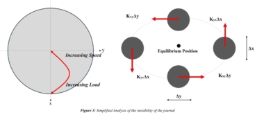
Cross-Coupled Forces and Stability
As this is a complex topic that requires dedicated explanation, one can visualize the impact of cross-coupled forces on journal stability by examining Figure 3. While the left-hand part of Figure 3 is theoretically simplified, the right-hand part shows a journal orbiting around its equilibrium position. Any excitation that drives journal movement (for example, in the x direction) will cause a respective movement in the y direction. The cross-coupled stiffness force then tries to pull the journal away from its equilibrium position, leading to the journal orbiting around it. As the cross-coupled forces increase, the journal is pulled further away from the equilibrium position leading to further disturbances in the oil film and hydrodynamic pressure and can potentially lead to an instability condition. Therefore, a detailed rotordynamics analysis is conducted, involving more detailed modeling of the journal bearing, during which stability is checked.