Verification & Validation
Three different rotor kits with particular balancing equipments will be considered.
a. Balancing Equipment: model TM2, analyzer RS 3164, transducer PMG 48/S and stroboscope BG-No 707.00.020
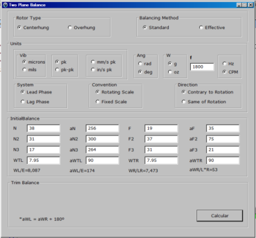
Rotor Type: Centerhung
Balancing Method: Standard
Units:Vib: microns pk, Ang: deg; W: g;f=1800CPM
Data: in p. 174 of Reference 15 of Reference 1
System-Convention-Direction:Lead Phase-Rotating Scale-Contrary to Rotation
Used: on-line software in Reference 5
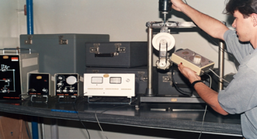
A>Data
N= 3.80000000000000E+001 d= 2.56000000000000E+002
F= 1.90000000000000E+001 e= 3.60000000000000E+001
Wtn= 7.95000000000000E+000 atn= 9.00000000000000E+001
N2= 3.10000000000000E+001 d2= 3.00000000000000E+002
F2= 3.70000000000000E+001 e2= 7.50000000000000E+001
Wtf= 7.95000000000000E+000 atf= 9.00000000000000E+001
N3= 1.70000000000000E+001 d3= 2.64000000000000E+002
F3= 3.10000000000000E+001 e3= 2.10000000000000E+001
Correction
Wn= 8.11252594400786E+000 an= 1.74367731945662E+002
Wf= 7.48493423362498E+000 af= 5.29374868807743E+001
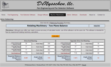
b. Balancing Equipment: rotor kit IRD Mechanalysis (model TM2 shown in the photograph), balancer Entek IRD 885, accelerometers IRD 970 and photocell Entek IRD 21000
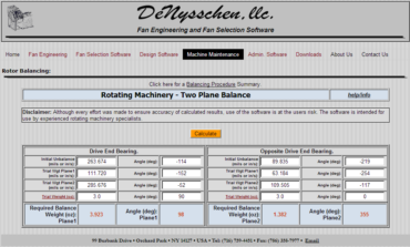
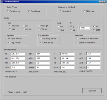
Rotor Type: Overhung
Balancing Method: Standard
Units: Vib:microns pk-pk, Ang: deg; W: g;f=2613CPM
Data: in Reference 1
System-Convention-Direction:Lead Phase-Fixed Scale-Same of Rotation
Used: on-line software in Reference 5
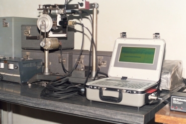
Table 1. Recorded data and corrections.
| Commonto all methods |
| N=263.674 mm |
d=114° |
F=89.835 mm |
e=219° |
| WTL=3.0 g |
aTL=90° |
|
|
| N2=111.720 mm |
d2=152° |
F2=63.184 mm |
e2=254° |
| Standard method |
| |
|
WTR=3.0 g |
aTR=0° |
| N3*=285.676mm |
d3*=52° |
F3*=109.505mm |
e3*=117° |
| WL*=3.942 g |
aL*=98° |
WR*=1.397 g |
aR*=355° |
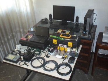
c. Balancing Equipment:prototype, analyzer MicroVib II DSS, accelerometers P/N 1880 and photo tachometer MINI-BEAM P/N 1015 BANNER
Rotor Type: Overhung
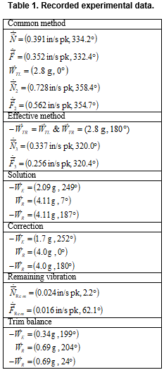
Balancing Method: Effective
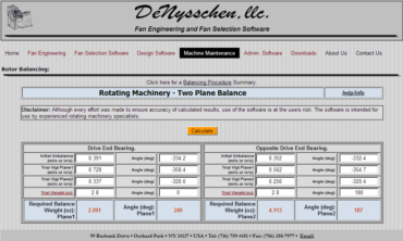
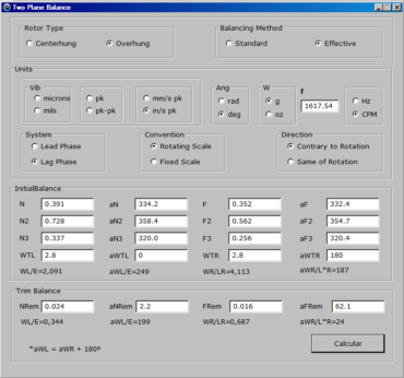
Units: Vib: in/s pk, Ang: deg; W: g; f=1617.54CPM
Data: in Reference 4
System-Convention-Direction: Lag Phase-Rotating Scale-Contrary to Rotation
Used: on-line software in Reference 5
Used: balance program in Reference 6 (Lead Phase-Fixed Scale-Same of Rotation)
Units: Vib: in/s pk ,Ang: deg; W: g;f = 1619.42CPM
New Data:
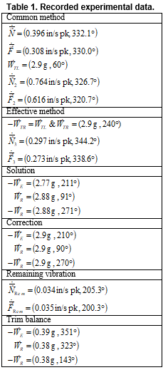
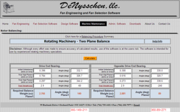
System-Convention-Direction: Lag Phase-Rotating Scale-Contrary to Rotation
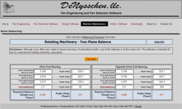
Used: invariance in Reference 3 and on-line software in Reference 5
Used: balance program in Reference 6 (Lead Phase-Fixed Scale-Same of Rotation)
Proof of item (c) to check the computer program
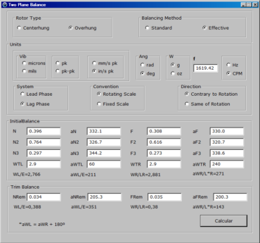
Conclusion: Comparable results were obtained for each case. Here, the verification of the computational solution is done by comparison with the standard solution. And, the validation of the computational model is done by comparison with the rotor kit.


