I. SCOPE OF WORK
I.A BACKGROUND
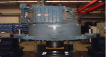
Due to unexpectedly high vibration levels in a newly commissioned chilled water pump located at Tampines Mall, Alstern Technologies Singapore Pte Ltd engaged SPM to conduct a comprehensive vibration analysis. This analysis involved on-site testing by SPM engineer, including run-up and coast-down tests. The resulting report provides a detailed assessment of the pump’s vibrational characteristics and offers recommendations to mitigate the observed high vibration and ensure optimal operational performance and extended service life. Data acquisition was performed using industry-standard portable instrumentation.
I.B TOOLS
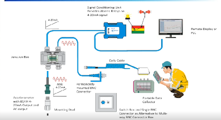
The following instruments were used to perform the vibration and bearing condition measurement:
· Leonova Diamond (HD Analysis, VIB/SPM HD Expert)
· Condmaster Ruby Software
· accelerometer (AC115-M12D)
I.C TEST CONDUCTED
· Vibration data were collected using Leonova Diamond on site by SPM Service Engineer
· Vibration data were imported to Condmaster Software for analysis.
I.D MEASUREMENT POINT LAYOUT

II. VIBRATION SEVERITY & CRITERIA LIMIT
II.A ISO 10816 STANDARD
Vibration measurement is a technique commonly used to identify and assess the magnitude of vibration in machinery or mechanical systems. It is an important technique in predictive maintenance and can help diagnose faults and abnormalities such as Imbalance, Misalignment, Mechanical Looseness, Bearing Faults, Gear Problems, Resonance and Electrical faults especially in the early stages. By measuring and analyzing vibration levels, maintenance professionals can make informed decisions about repairs and replacements, leading to cost savings and reduced downtime.
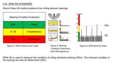
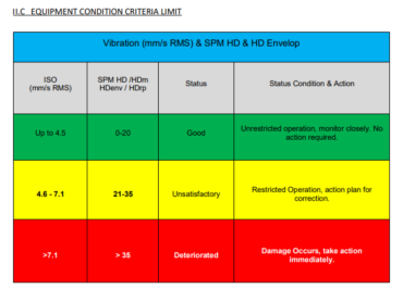
The root mean square (RMS) value of vibration velocity, measured in mm/s (or inch/s), is utilized as a criterion for categorizing machines into three distinct classifications: “Good”, “Unsatisfactory” or “Deteriorated”.

ISO 10816 Part 3 Standards classifies industrial machinery in following groups:
Group 1: Large machines with rated power above 300 kW and not more than 50 MW.
Group 2: Medium-sized machines with rated power above 15 kW up to and including 300 kw.
Group 3: Machines with rated power above 15 kw with external driver and radial and axial mixed flow.
Group 4: Machines with rated power above 15 kw with integral driver and radial and axial mixed flow.
II.D SUMMARY AND RECOMMENDATION
Recommendations
The following recommendations are made to mitigate the identified vibration problems:
Addressing System Resonance
• Operational Adjustments: Avoid operating the pump at speeds that excite the resonant frequencies (approximately 70% and 90% of the rated speed, based on the observed resonance frequencies). A detailed analysis of the pump’s operating speed versus vibration amplitude should be conducted to precisely determine the problematic speed ranges.
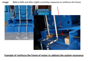
• Structural Reinforcement: If avoiding the resonant speed ranges is not feasible, structural reinforcement of the motor base frame is recommended. This may involve adding stiffeners, increasing the base’s mass, or other modifications to shift the natural frequencies away from the operating range.
Addressing Shaft Imbalance
• Source Identification: Conduct a motor solo run test to isolate whether the imbalance originates from the motor or the pump. This involves disconnecting the pump from the motor and running the motor independently to measure its vibration levels.
• Balancing: If the imbalance is confirmed, field balancing of the rotor (either motor or pump, depending on the source identified) is necessary. This involves adding or removing weight at specific locations on the rotor to correct the imbalance.


IV. CONCLUSION
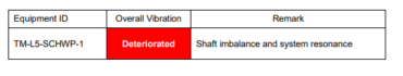
In conclusion, the high vibration levels observed are primarily attributed to system resonance and shaft imbalance. These issues, if left unaddressed, can lead to premature bearing wear, seal failures, and ultimately, catastrophic pump failure.
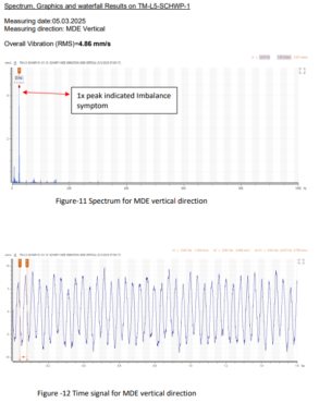
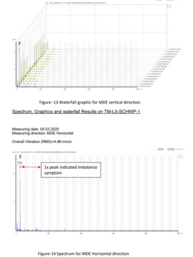
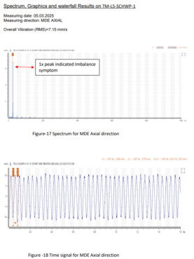
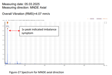
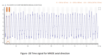
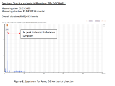
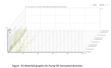
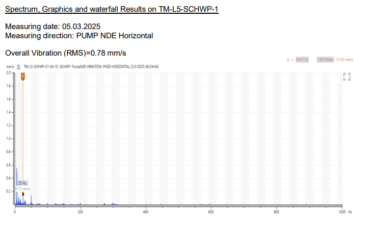
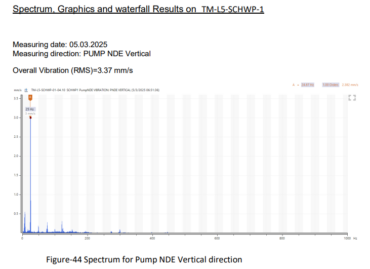
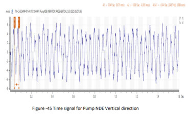
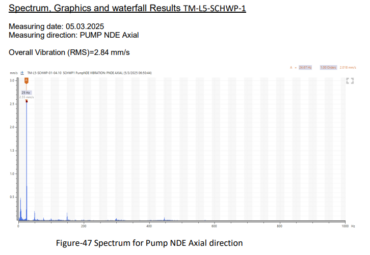
During normal operation at 100% speed, the overall RMS vibration exceeded the alarm limit of 7.1 mm/s specified in ISO 10816-3. Significant 1X frequency peaks were observed at both the MDE and PDE, indicating a strong correlation with the pump’s rotational speed. Specifically, a peak(1X) amplitude of 4.88 mm/s was measured in the horizontal direction at the PDE, and a peak(1X) of 6.61 mm/s was observed in the axial direction at the MDE. These findings strongly suggest shaft imbalance as a primary contributor to the high vibration. Evidence of shaft imbalance was detected at both the motor drive end (MDE) and pump drive end (PDE). Shaft imbalance generates centrifugal forces that cause vibrations, particularly at the rotational frequency.
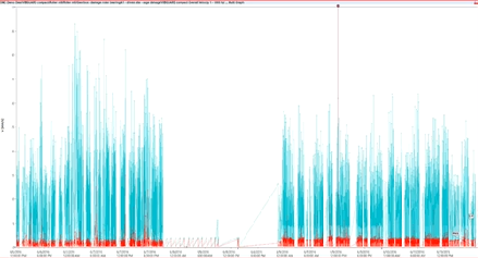
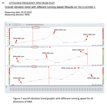
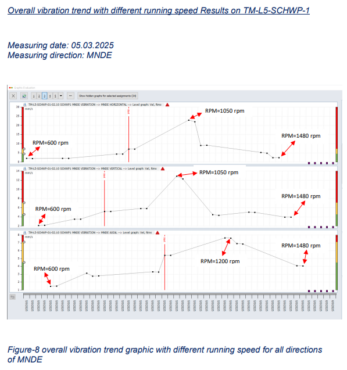
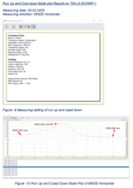
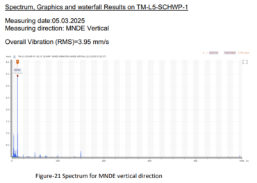
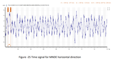
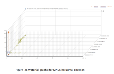
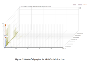
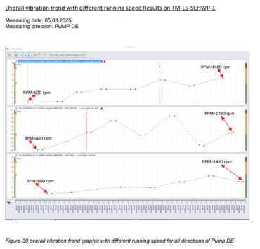
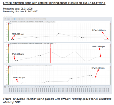
The run-up/coast-down test yielded significant fluctuations in overall root mean square (RMS) vibration levels, ranging from a minimum of 1.19 mm/s to a maximum of 26.69 mm/s. The identification of pronounced vibrational peaks at 1015 rpm (26.69 mm/s) and 958 rpm (26.46 mm/s) strongly suggests the presence of resonant frequencies within the system’s operational parameters. A pronounced peak amplitude of 22.49 mm/s was observed at 1X frequency in the horizontal direction at the MNDE during operation at 70% speed during taking vibration measurement with different running speed.
This confirms the presence of a system resonance frequency, exacerbating the vibration levels.
System resonance was observed within specific frequency ranges:
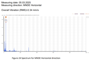
• Horizontal Direction (MNDE): 15.9 Hz – 17.5 Hz
• Axial Direction (MDE): 22.5 Hz
Recommendations:
The following recommendations are made to mitigate the identified vibration problems:
Addressing System Resonance
• Operational Adjustments: Avoid operating the pump at speeds that excite the resonant frequencies (approximately 70% and 90% of the rated speed, based on the observed resonance frequencies). A detailed analysis of the pump’s operating speed versus vibration amplitude should be conducted to precisely determine the problematic speed ranges.
• Structural Reinforcement: If avoiding the resonant speed ranges is not feasible, structural reinforcement of the motor base frame is recommended. This may involve adding stiffeners, increasing the base’s mass, or other modifications to shift the natural frequencies away from the operating range.
Addressing Shaft Imbalance
• Source Identification: Conduct a motor solo run test to isolate whether the imbalance originates from the motor or the pump. This involves disconnecting the pump from the motor and running the motor independently to measure its vibration levels.
• Balancing: If the imbalance is confirmed, field balancing of the rotor (either motor or pump, depending on the source identified) is necessary. This involves adding or removing weight at specific locations on the rotor to correct the imbalance.
However, it is important to acknowledge that the analysis may have certain limitations, such as data availability or system complexity. Continuous monitoring of vibration levels is strongly recommended to ensure optimal pump operation and prevent potential issues.
Onsite Measurement: Aung Zay Yar Min
Date of Measurement: 05/03/2025
Reported by: AUNG ZAY YAR MIN
Compile & Submitted Date: 11/03/2025