Visual Inspection of Couplings and Machinery Components
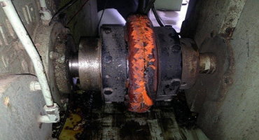
Some things just don’t pass the “eye test.” Your eyes are actually great tools for seeing things that are not straight, not plumb, not level (pictures hanging on a wall for example), not right. Many times, just by looking at a coupling you can tell “it’s not aligned,” and you are usually correct.
Visual Inspection: In maintenance facilities, this means inspection of equipment and structures using any or all of our raw human senses such as vision, hearing, touch, and smell and/or any non-specialized inspection equipment.
Here are some examples:
See Coupling Dust = Misalignment
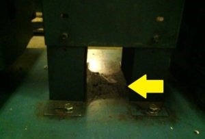
Hmm, maybe a base problem? Not maybe, it IS a base problem. The washers, under the corner, were probably used to stiffen the base to correct a resonant base amplifying vibration levels. Ok for a short-term fix, but it is not the solution.
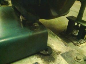
Using a straight edge for the alignment? You can see there is a gap on one side of the coupling. Parallel (offset) misalignment for sure. And I will argue you have no idea what the angular misalignment is. (A straightedge should be used only for “roughing in” during the pre-alignment steps.)
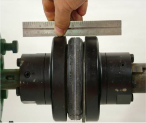
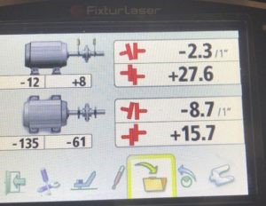
This pump was aligned using a straight edge. The mechanic did a good job considering the alignment tool he was using. If you are good at using a straight edge, you can regularly get the parallel/offset values close to or within the tolerance. In this case, for 1800 rpm, the parallel/offset values met tolerance (+/- 4.0 mils or better). The angular misalignment is another story; the values are considerably out of tolerance (more than +/- 0.7mils/1”).
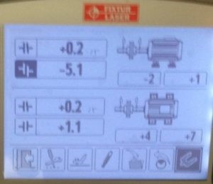
It is difficult, almost impossible, to see the angular relationship between the movable and stationary machines with a straight edge and correct it. (This, and the other measurement results below, were done with Fixturlaser Laser Shaft Alignment tools.)
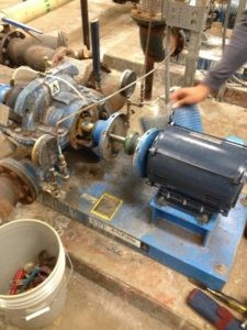
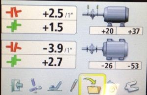
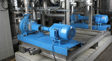
Motor-Pump Packages: You were told “it was factory aligned.” What does that even mean? Aligned to what tolerance? Was it truly aligned to industry standard tolerances at the factory before being shipped? Was it shipped and moved into place? Was it aligned before piping was hooked up? Was it aligned before the electrical conduit was attached to the motor?
These 4 motor pump packages had similar results, the classic straight edge result: the parallel/offset misalignment is good, the angular misalignment not so good. The biggest problem with this is that, over time, angular misalignment has the most damaging effects on roller element bearings and pump seals.
In all these scenarios it will need to be re-aligned!
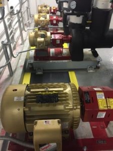
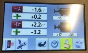
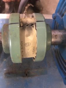
Have you ever seen a blond-colored coupling insert? This coupling insert changed color due to excessive heat buildup over time, and you can see the insert “split” doesn’t match up either. The alignment results show why it got so hot!
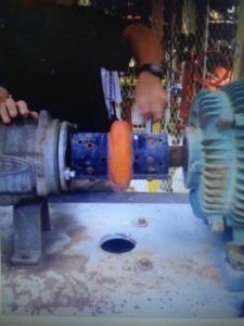
If you see this coupling type, it needs to be removed, then you need to perform an uncoupled shaft alignment. Even though this type of coupling is considered a flexible coupling, measurement results testing has shown them to behave like rigid couplings. Measurement values coupled vs uncoupled are vastly different.
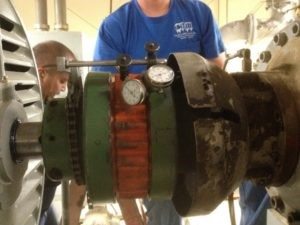
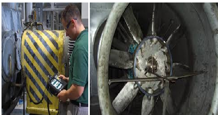
In almost all cases, when aligning with dial indicators, you must compensate for bar sag. The mechanic did a great job of alignment; however, he didn’t compensate for the 0.005″ (5.0 mil) of bar sag.
Vision, Hearing, Touch and Smell. Use them! Trust them!




Salam
What effect the gab between halves of flexible coupling?
And how can determine it
Thank u
With best regards
Depending on the type of coupling, the coupling gap can have an effect on vibration, coupling heat/wear, and bearing thrust. It is best to go by the coupling manufacturer’s specifications on setting the proper gap. The best way to determine if it is a problem is simply to measure the gap, and compare it to the coupling manufacturer’s specifications.