Two Minute Tips  

What is Dissipation Factor?

Mark Koch | Technical Support Manager, ALL-TEST Pro, LLC

Dissipation Factor is an electrical test that helps define the overall condition of insulating material.

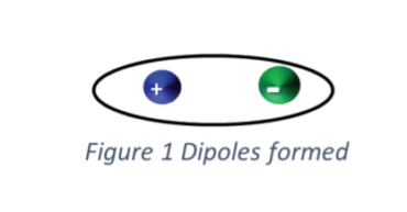
A dielectric material is a material that is a poor conductor of electricity but an efficient supporter of an electrostatic field. When an electrical insulating material is subjected to an electrostatic field, opposing electric charges in di-electric material form di-poles.

Dipoles Formed - Mobius InstituteA capacitor is an electrical device that stores an electrical charge by placing a dielectric material between to conductive plates. The Groundwall Insulation (GWI) system between the motor windings and the motor frame creates a natural capacitor. The traditional method of testing the GWI is to measure the value of the resistance to ground. This is a very valuable measurement for identifying weaknesses in the insulation but fails to define the overall condition of the entire GWI system.
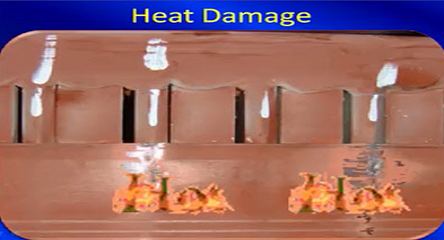
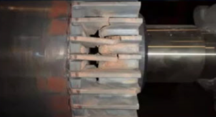
The Dissipation Factor provides additional information regarding the overall condition of the GWI.

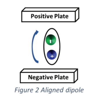
In the simplest form when a dielectric material is subjected to a DC field the diploes in dielectric are displaced and aligned such that the negative end of the dipole is attracted toward the positive plate and the positive end of the dipole is attracted toward the negative plate. Some of the current that flows from the source to the conductive plates will align the dipoles and create losses in the form of heat and some of the current will leak across the dielectric. These currents are resistive and expend energy, this is resistive current IR. The remainder of the current is stored on the plates current and will be stored discharged back into the system, this current is capacitive
current IC.

When subjected to an AC fi eld these dipoles will periodically displace as the polarity of the electrostatic field changes from positive to negative. This displacement of the dipoles creates heat and expends energy. Simplistically speaking, the currents that displace the dipoles and leaks across the dielectric is resistive IR, the current that is stored to hold the dipoles in alignment is capacitive IC.

Dissipation Factor is the ratio of the resistive current IR to the capacitive current IC, this testing is widely used on electrical equipment such as electric motors, transformers, circuit breakers, generators, and cabling which is used to determine the capacitive properties of the insulation material of the windings and conductors. When the GWI degrades over time it becomes more resistive causing the amount of IR to increase. Contamination of the insulation changes the dielectric constant of the GWI again causing the AC current to become more resistive and less capacitive, this also causes the dissipation factor to increase. The Dissipation Factor of new, clean insulation is usually 3 to 5%, a DF greater than 6% indicates a change in the condition of the equipment’s insulation.Aligned Dipole - CBM CONNECT

When moisture or contaminants are present in the GWI or even the insulation surrounding the windings, this causes a change in the chemical makeup of the dielectric material used as the equipment’s insulation. These changes result in a change in the DF and capacitance to ground. An increase in the Dissipation Factor indicates a change in the overall condition of insulation, comparing DF and capacitance to ground helps determine the condition of insulation systems over time. Measuring the Dissipation Factor at too high or too low temperature can result in unbalanced results and introduce errors while calculating. IEEE standard 286-2000 recommends testing at or around ambient temperature of 77 degrees Fahrenheit or 25 degrees Celsius.

Subscribe
Notify of
guest

This site uses Akismet to reduce spam. Learn how your comment data is processed.

1 Comment
Oldest
Newest Most Voted
Inline Feedbacks
View all comments
felipe jimenez
8 months ago

hello
i have a question; what to do when dissipation factor is 100 %? i use the all pro test 7 for this test.
DF>100%
C=30.68 nF

About the Author

Mark Koch Technical Support Manager, ALL-TEST Pro, LLC

Mark Koch is a member of the Technical Support team at ALL-TEST Pro, LLC (ATP), where he has provided professional support worldwide for users of ATP equipment since 2014. He has 17 years of electrical and reliability maintenance experience. In 2001, he started his career as a construction electrician. During this time, he worked his way up from shop floor apprentice to a foreman in charge of starting and completing remodel and new construction projects. In 2010, he began working at the Metropolitan Sewer District (MSD) of Greater Cincinnati, Ohio, USA, where he learned electrical maintenance best practice and helped implement a predictive maintenance program (PdM). During his service at MSD, his team was the recipient of both the Uptime Magazine’s Best Emerging Maintenance Reliability Program Award and the Uptime Magazine’s Best Asset Condition Management Program Award. At MSD, he learned and provided routine PdM services such as thermography, vibration, lubrication, visual inspection, motor testing, and ultra-sonics.


Education and Certifications:

2001-2006- International Brotherhood of Electrical Workers (IBEW) Apprenticeship Program and the National Electrical Contractors Association (NECA) Inside Wireman Certification.

2013- PdM Visual Testing Level 2 Certification & Level 1 Thermographer Certification; 2014- Vibration Analysis Level 1T Certification.